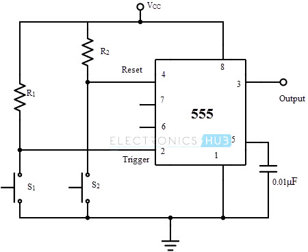

Operation of Monostable Multivibrator mode of 555 timer IC: Power or VCC: It is connected to positive voltage (+3.6v to +15v). Whenever the output goes low or the flip-flop gets reset, the discharge pin is pulled to ground. DISCHARGE: This pin is drawn from the open collector of transistor. Since the transistor (on which discharge pin got taken, Q1) got its base connected to Qbar. Then a voltage equal to or greater than VCC*(2/3) (i.e.6V for a 9V supply) will reset the flip-flop. The threshold pin is drawn from positive input of comparator1. THRESHOLD: Threshold pin voltage determines when to reset the flip-flop in the timer. Normally this pin is pulled down with a capacitor (0.01uF), to avoid unwanted noise interference with the working. Control Pin: The control pin is connected from the negative input pin of comparator one. This pin is connected to VCC for the flip-flop to stop from hard resetting. Reset pin is directly connected to MR (Master Reset) of the flip-flop. Reset: There is a flip-flop in the timer chip. This is output pin where Load is connected. OUTPUT: This pin also has no special function. If this pin is connected to ground (or less than Vcc/3), the output will be always high. With the comparator two output high we get high voltage at the timer output. The comparator two output is connected to SET pin of flip-flop. TRIGGER: Trigger pin is dragged from the negative input of comparator two.


 0 kommentar(er)
